
Our website describes the supported data rates for Board to Board Connectors and FPC / FFC Connectors.
Both are defined based on the "differential 100Ω system", but we sometimes receive questions from inside and outside the company, "What about using a single end?" Regarding the details, we will respond after confirming the situation, but unfortunately, in most cases, the answer will be "at least the same performance cannot be expected ...".
The first conclusion about the title "Difference in connector performance between single-ended and differential transmission" is that the main reason for the difference is Compared to differential transmission, which transmits by coupling/coupling inverted signals, single-ended transmission is much more dependent on surrounding "installed metal" such as shields and other connector pins. That's it.
In recent years, especially from the viewpoint of EMC, differential transmission has become the mainstream for high-speed transmission communication within a board. That doesn't mean that the need for single-ended, high-speed transmission connections has disappeared. On the other hand, differential transmission and single-ended transmission require different approaches to construct high-quality transmission lines. Many coaxial connectors/cables for single-ended transmission continue to be active in the market, and we are also introducing a connector that achieves high-speed single-ended transmission with a non-coaxial structure as an in-Onboard Coaxial Camera Solution.
However, they are slightly different from the connectors used for high-speed differential transmission. In this article, I would like to explain the reasons for the differences in connectors based on the characteristics of differential transmission and single-ended transmission, as much as possible in a way that can be grasped as an image.
Broadly speaking, there are three types of signal transmission modes on transmission lines, each of which is called differently. Table 1 summarizes. Also, please refer to our Glossary, which explains differential signals.
| Ordinary 2-core transmission (single-ended) |
differential transmission | Common mode | |
|---|---|---|---|
| Main names and combinations | imbalance | equilibrium | ― |
| Unbalance | balance | ― | |
| Single-ended transmission | differential transmission | common mode transmission | |
| Single-ended transmission | Differential | Common mode | |
| ― | odd mode | even mode |
Table 1 Three transmission modes
What are they like? An example of sending the following signal will be explained.


Figure 1 Ordinary 2-core transmission/single-end
This is the simplest transmission mode. In this method, a signal voltage is applied to the signal line with respect to the reference 0V line (ground/GND). The output signal is the potential difference from the reference of the signal line at the exit side. As long as the signal line is not adversely affected or degraded while passing through the signal line, the signal can be retrieved as it was input at the exit.

Figure 2 Differential transmission
Next is differential transmission. In addition to the transmission of (1), a line (signal line (2)) that applies the inverted version of the signal to be sent is added. The reason for this and its merits will be explained in a later section. At the output side, the "difference" between the positive signal and the inverted signal is taken and restored to the original signal, so it is called differential transmission. Another feature is that transmission can be established without providing a GND line as a reference.

Figure 3 Common mode transmission
Finally, there is common mode transmission. Contrary to differential, it is a method in which the same phase signal is sent on two lines. This method alone is not used for transmission. Rather, it is often treated as a noise source. As for the aspect of signal transmission, it can be used as a secondary signal transmission during differential transmission because it is easy to separate the differential signal at the output side.
What does it mean to be easy to separate? When addition is performed at the output, the differential signal disappears and the common mode doubles. Conversely, when subtraction is performed, the common mode signal disappears and the differential signal doubles. . Therefore, it is used as a method of sending multiple different signals that can be separated at the exit side. A common-mode signal is usually much slower than a differential signal sent at the same time.
The general configuration of each mode is as above, but what are the characteristics of each mode, especially what are the benefits? Of the three transmission modes, (3) common mode is not a mainstream transmission method, and can be regarded as a sub-stream of single-ended transmission, so I would like to focus on single-ended transmission and differential transmission. Before proceeding there, Figure 4 shows an image comparison of ordinary single-ended transmission and differential transmission.
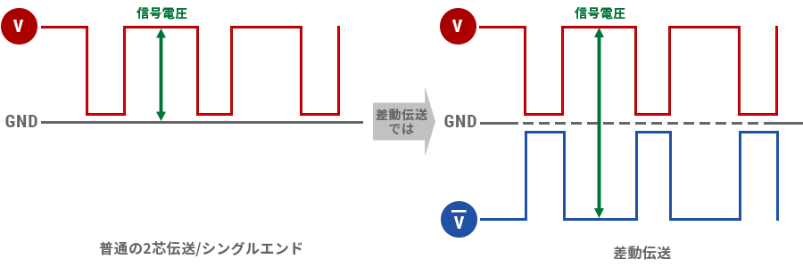
Fig. 4 Image comparison of single-ended transmission and differential transmission
First of all, I think this is an advantage of single-ended transmission, but the configuration of the transmission line for the signal is simple, so the connection between them is also simple. Figure 5 is a three-dimensional drawing of the figure in the previous section.

Ordinary 2-core (1-core to GND) transmission

differential transmission
Fig. 5 Comparison at 1 lane
However, there are cases where differential transmission does not require a GND plane, so this does not seem to have much of an advantage.
But what about sending multiple signals? Figure 6 is an image diagram when four signals are sent simultaneously. GND can be common for both single-ended and differential transmission. Also, in both cases, a GND line may be inserted between each signal line as a countermeasure against crosstalk, but it is omitted here.

multiple differential transmission

Multiplexed single-ended transmission with common GND
Fig. 6 Comparison with multiple lanes
A comparison of Figure 6 shows that single-ended transmission is much simpler than differential transmission, while differential transmission requires many extra lines. This is a huge advantage of single-ended transmission and a disadvantage of differential transmission. Therefore, single-ended transmission is the mainstream, especially for low-speed transmission connectors that do not require stringent quality as a transmission line. So why is differential transmission used, especially in High-speed transmission Connector, despite such disadvantages?
The reason differential transmission is used in High-speed transmission Connector is that it is "more tolerant of noise" than single-ended transmission.
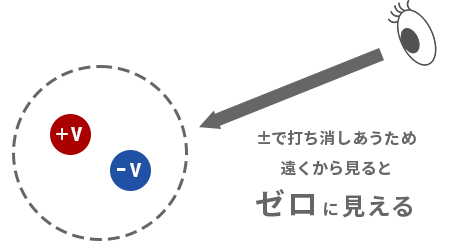
First of all, I would like you to have a simple image of "making noise". A differential signal consists of a positive signal and an inverted negative signal. "+" and "-". When combined, they cancel each other out. Therefore, if you grasp it very simply, it will be an image like Fig. 7.
In addition, let's have a little more technical image in Fig. 7. Noise occurs especially when the signal changes. The noise generated at that time depends on the "way of change". In a differential signal, the signals on adjacent lines change in completely opposite behavior, so "exactly opposite" noise is generated from each. Therefore, although not completely, noise cancels out each other "relatively", so differential transmission is "difficult to emit" noise compared to single-ended transmission.
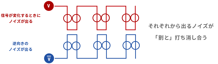
Figure 7 Differential transmission and noise generation
Here's a little bit of trivia. Around 2001, there was a method that was proposed to realize a low-cost device with a small number of lines like a single-ended while maintaining the goodness of low EMI and low emission of the above-mentioned differential (for those who are interested,” Try searching for "JAZiO"). As a rough image, it is "to send the sum of the inverted signals to multiple signal lines at once on another line". A simple illustration is shown in Fig. 8.
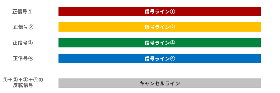
Fig. 8 Overview of JAZiO concept
Certainly, this method satisfies the requirement of "zero when seen from a distance". Due to the physical distance between the signal and cancellation lines, it is likely to have "somewhat" low-emission properties, if not as purely differential. However, while differential transmission was taking over high-speed signals, we never heard of this method being applied to practical devices. Perhaps one of the reasons for this is that this method could not be expected to have the "benefits of differential transmission when subjected to noise," which will be explained next.
Now let's talk about what happens when you get that noise. Figure 9 is an image diagram of a differential signal line subjected to external noise. In a differential signal, the lines of the positive signal and the inverted signal are located relatively close to each other, mainly adjacent to each other, so they are each subject to "similar noise effects". Now, as explained earlier, in differential transmission, each output is "subtracted" at the exit. At this time, most of the "similar noise" is eliminated, making it less likely to affect the signal.
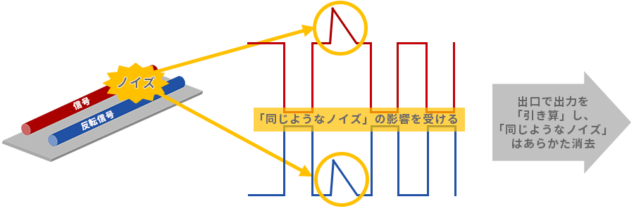
Fig. 9 Differential line image with external noise
As many of you may have noticed, this is similar to the relationship between common mode transmission and differential transmission. External noise attacks signal lines as common mode noise. Differential transmission has a mechanism to cancel this, so compared to single-ended transmission, it is more susceptible to noise and stronger in terms of EMS/immunity.
The advantage of differential transmission is the reduction of return current due to coupling (some people may think that it will be 0, but if there is a GND plane, it will actually remain a little), which reduces resistance loss, etc. I have. Another issue in differential transmission is how to reduce the deviation from 180°, and this becomes more severe as the frequency increases (this is assessed by parameters such as skew and common mode conversion). .
Table 2 summarizes the comparisons so far. Advantageous ones are highlighted in red.
| single end | Differential | |
|---|---|---|
| Number of lines/connections | little | Many |
| EMC resistance | weak | strength |
| Low loss/long distance transmission (comparison) | somewhat unfavorable | Somewhat favorable |
| Intra-channel phase difference management | unnecessary | required |
Table 2 Comparison of merits and demerits of single-ended and differential
Next, we will finally talk about the difference in connector performance, which is the main topic of this article, in other words, the reason why there is a difference in the appropriate transmission line structure. It's a little confusing, but I'd like to talk about the structure of the line while imagining the "electric field" that is formed around the line (strictly speaking, the magnetic field should also be considered, but it's easy to imagine. I will focus on the electric field with priority).
First, let me explain what an electric field is. I will give priority to simple understanding over accuracy, so I hope that those who have studied electromagnetism at university can skip it.
First the charge is defined. To put it plainly, it's electric energy, and to put it more closely, it's like that static electricity that builds up in your body. Around this charge, a field called an electric field is generated that affects the surroundings. This is strong near the charge and weakens as it goes farther away. At infinity or a grounded conductor, this electric field disappears. I drew the image of the electric field where one electric charge is in space with blue gradation on the left side below. "If there is nothing to hinder it," it will be like this. On the right side of it, I wrote the electric lines of force in red. The lines of electric force are drawn as arrows in the direction of the electric field, with the number of arrows corresponding to the strength of the original charge. Therefore, it is useful for visually grasping the state of electric field formation.
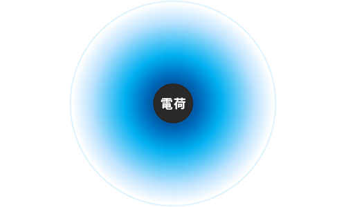
An electric field (electric field) is generated around the electric charge and is stronger around the electric charge.
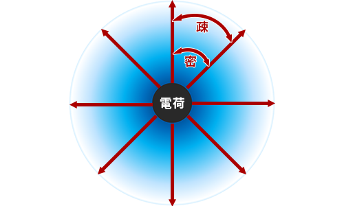
Draw lines of electric force corresponding to the strength of the charge in the direction in which the electric field is generated
The electric field is relatively dense, and becomes sparse as it becomes weaker.
Fig. 10 Electric field and lines of force, charge and current
The illustration shows the simplest state, but this electric field is affected by other electric charges or conductors in the surrounding area that attract or repel each other's electric fields. Also, the charge can be defined as positive = “+” and negative = “-”. Like signs repel each other and opposite signs attract each other.
Now, it is fine to say that when a signal flows, a current flows. Electric current is the movement of charges. A similar electric field is generated around a conductor carrying current. In the case of an alternating current, if you stay in the same place, the strength of the "original" of the raised electric field will change. Inverted signals such as differential signals can be regarded as positive and negative charges and can be replaced in the same way. Therefore, from now on, I would like to look at the state of the electric field in single-ended and differential transmission, as the state of the lines of electric force when the signal is replaced with a positive charge or a negative charge.
Below is an image of the electric field of single-ended transmission and differential transmission due to electric lines of force when there is no reference = GND. As you can see, there is a feeling that the electric field is trying to "close" in differential transmission. This is due to the fact that the electric field tries to settle due to the inverted signals, '+' and '-' coupling/coupling below.
On the other hand, in single-ended transmission, it diverges radially.

Electric field around single-ended transmission

Electric field around differential transmission
Fig. 11 Electric field around single-ended transmission and differential transmission
It may sound a little rough, but if this electric field is not contained, the characteristic impedance, which is the basic performance of the transmission line, will not be stable. In the design of transmission lines and connectors, differential transmission, which is already fairly well settled, is relatively flexible, but in single-ended transmission, it is necessary to somehow suppress this wild electric field. For this reason, connectors optimized for high-speed differential transmission do not exhibit the expected performance because the electric field of single-ended signals does not subside.
Then, what can be done to suppress the electric field that radiates is to install a grounded metal around it (it sounds like a pun...). Electric lines of force hit the GND plate perpendicularly and end there. For example, when the electric field diverges like in the single-ended transmission above, and it is covered with a grounded metal object, etc., it will be reborn as an extremely stable line (it will become a coaxial structure described later). Even if it doesn't go that far, it is necessary to calm down the electric field with a suitable reference = GND. I think this is a relatively easy-to-understand example, so I will explain how to set up a GND plate to make a single-ended electric field behave like a differential one.
Place a sufficiently long GND plate = shield on the left side of the single-ended transmission line. I wrote that "the electric lines of force penetrate the GND plate perpendicularly and end there", but this makes the electric lines of force behave as if the "self reflected in the mirror" is needed on the other side of the shield. It's a mirror, so it's reversed. The image is drawn in Fig. 13, and this is exactly what differential transmission is. Looking at it the other way around, differential transmission can be viewed as having a large virtual GND plate already. It is because of this virtual reference that "transmission is possible without providing a reference GND line" as described in the explanation of differential transmission. This makes them "relatively flexible" in connector construction for high-speed transmission.
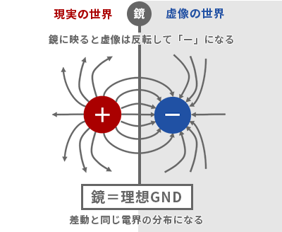
Figure 12 Mirror effect and differential transmission
As you can see, I hope you can imagine that even with single-ended transmission or with a single GND plate, the electric field can be controlled to the extent of a differential. However, in practice, it is often not realistic to have a "sufficiently long (strictly infinite) shield above and below", for example in a connector. In addition, although the above figure is a cut-out of a certain cross section, the shield must have sufficient length in the front and back to maintain the state of this electric field. When the electric field is interrupted, it returns to the original rampage again. In addition, if the mirror is cloudy or scratched, the mirror image will be blurred. In order to correctly reproduce the state equal to the differential, the electrical resistance value of the shield must be zero (it is superconducting). hey).
Therefore, in reality, for high-speed single-ended transmission, it is necessary to arrange the shield part that will be the GND plane in a "good manner" while devising the characteristics of the metal used for the shield and structural restrictions. To that end, I think the shortest route is to know the coaxial structure, which is the most perfect state for transmission lines and connectors, as opposed to the state without a shield, so let's move on to that.
I explained that "the reference (GND) is more important for single-ended transmission," and that the line for single-ended transmission is "extremely stable when covered with a grounded metal object." If you actually cover the surroundings, it will look like the image below.
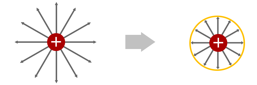
Fig. 13 Stable single-ended transmission when covered with a grounded metal object, etc.
A structure that has a reference on a concentric circle with the same axis as the signal line is called a "coaxial structure" as it is. The electric field is neatly contained while maintaining the original directionality of the electric lines of force. Also, you can see that the electric field in space (distribution of electric lines of force) is arranged very neatly. With such a clean and regular electric field structure, the characteristic impedance, which is an important characteristic of a line, can also be expressed in a relatively simple form.
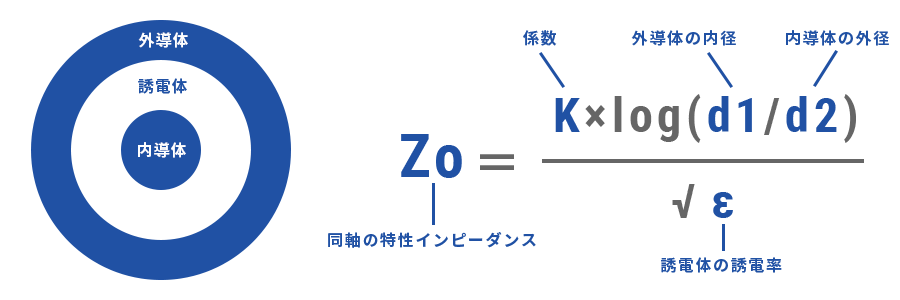
Fig. 14 Basic configuration and characteristic impedance of coaxial line
It is uniquely determined by the ratio of the diameters of the inner conductor, which is the line, to the outer conductor, which is the reference, and the permittivity of the dielectric to be filled. Therefore, it is relatively easy to adjust the characteristic impedance of the coaxial structure. As a single-ended transmission line, it is truly a simple is best answer.
In a Mating, the key to improving performance is how to maintain the coaxial structure even at the connecting part. I'm sorry...)
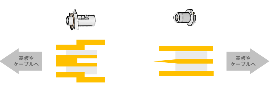
Fig. 15 Image of Mating portion of coaxial connector
This single-end transmission + coaxial structure is the strongest for high-speed transmission as a transmission line or connector. As I said, "relatively flexible" in differential transmission, it is easier to configure lines and connections for high-speed transmission than single-end up to a certain area. There is no such thing as a perfect match like a combination. For example, when sending signals in the millimeter-wave band, sometimes the simplest way to ensure performance is currently to "kill the coupling" in the differential and send with two coaxial cables.
On the other hand, the coaxial structure is accompanied by the challenges of achieving low cost and realizing in conjunction with functions other than high-speed transmission.
Coaxial connectors meet the required performance by locally deviating from the coaxial structure to improve usability, add functions, or reduce costs. The most common method is to deviate from the coaxial structure of the mounting part with the board. When workability is prioritized, it deviates greatly, and when performance is critical, the coaxial structure is maintained to the utmost limit to minimize deviation. increase. There are also some Floating structure coaxial connectors that have a spring added to the connecting part with the board to provide the Floating structure / Floating function, and a mortar-shaped receptacle that allows the connector to shift as shown in Fig. 17. has been commercialized by a connector manufacturer (the latter has also been standardized).
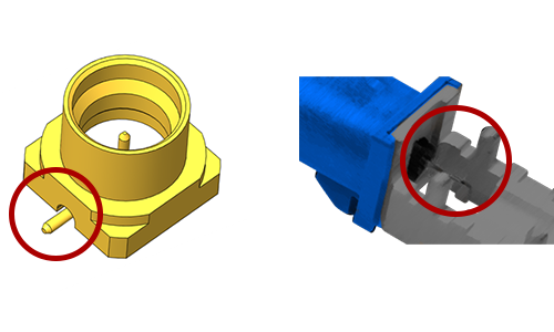
Deviation from the coaxial structure of the board mounting part
Allows movement with a mortar-shaped saucer
Fig. 16 Deviation from coaxial structure
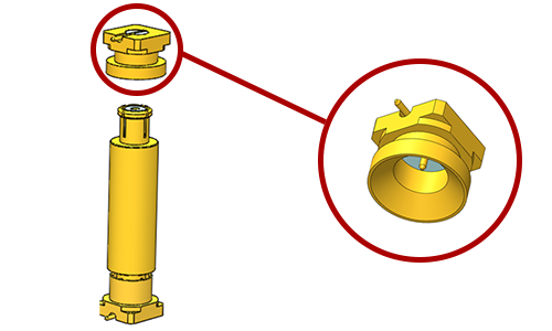
We have not commercialized it yet, but this area is also a development target as "Floating structure IRISO". This is part of the concept drawing.
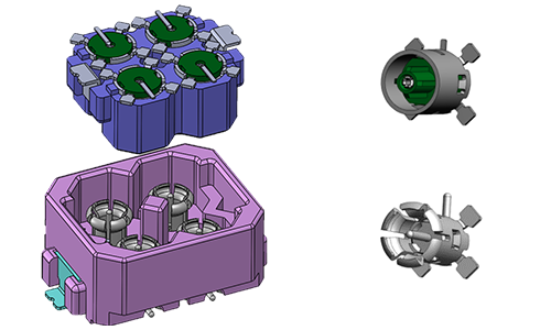
Fig. 17 Conceptual diagram of Floating multiple coaxial
On the other hand, there are also cases where the structure is moved closer to the high-speed transmission performance of coaxial from a non-coaxial structure. I think many people of a certain age remember that DVI, which was the standard IF for displays that was once mainstream, was used for analog single-ended transmission, with a cross-shaped GND for coaxial There was a terminal that reproduced a state close to
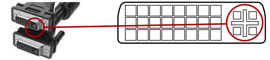
Figure 18 DVI connector
Also, for the backplane, many GND and shields are used in the connector to support single-ended transmission, and you can see that it is getting closer to the coaxial state. The compression connector for coaxial is one of them, which is introduced in our case study "In Onboard Coaxial Camera Solution". By appropriately arranging metal parts that serve as a reference = GND in a Floating compression type connector, it becomes a connector that achieves pseudo-coaxial performance despite its non-coaxial structure.
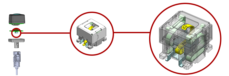
Fig. 19 Compression connector for Floating coaxial
Thus, for high-speed single-ended transmission, the coaxial structure becomes the "textbook" and deviations from it and approximations from other structures make the application fit. In particular, the latter is the practice of ``arranging the shield part that will be the GND plane,'' as mentioned in ``The reference = GND is more important for single-ended transmission''. In a connector for single-ended transmission, in which the electric field is emitted as it is, the method of providing this shield is much more important than in a differential connector.
The theme of this time is quite difficult to explain in a concise manner, and I am sorry that it has become quite a volume... Even though it supports XX Gbps and YY GHz, there are differences between differential transmission and single-ended transmission, connector development I would appreciate it if you could understand that the vectors of are also different. Also, I would be very happy if there were people who became interested in this article and researched or learned more about it. Or, I would be very happy if I could receive comments such as "Isn't that way of thinking different?"
IRISO has released several products to the world that have added additional functions to high-speed differential transmission connectors. As for single-ended transmission, we have had opportunities to see it little by little, and we are continuing to work diligently on other developments. That's not what our company is like by simply "supporting high-speed transmission", so we will continue to devote ourselves to making it a product that has some other functions and advantages until the day it catches everyone's attention!
Here you can find information about our various initiatives for high-High-speed transmission Connector and in Onboard Coaxial Camera Solution. Please take a look.